
📚 Course contents
Electronics Concepts, lesson 15 of 19
How Does a Bridge Rectifier Work? Simplified
Short answer: a bridge rectifier is four diodes arranged in a square. AC pushes current one way, then the other. In each half of the wave, two diodes switch on and steer the current so it always flows the same way through the load. Out comes bumpy DC, which a capacitor then smooths.
Every phone charger, laptop adapter and Arduino power supply has one inside.
First: AC and DC
DC flows one way, like a river. AC (India's mains is 230 V, 50 Hz) changes direction 50 times a second, like a saw going back and forth. Electronics needs DC, so the very first job of a power supply is to stop the back-and-forth.
The building block: a diode is a one-way gate
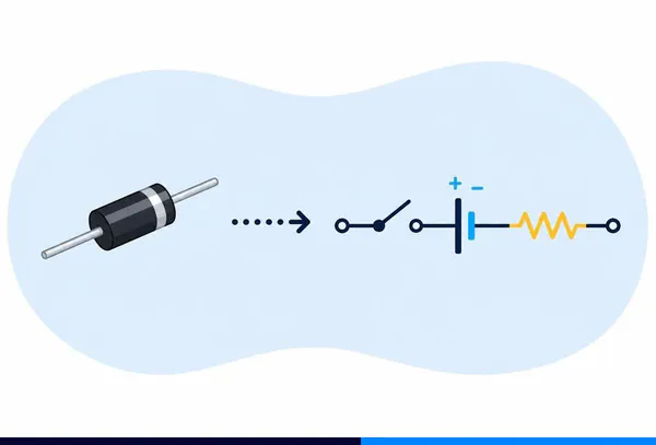
A diode lets current through in one direction only. Push it the right way (forward bias) and the gate swings open, dropping about 0.7 V. Push the other way (reverse bias) and it stays shut.
Forward bias: + is on the anode, so the diode acts like a closed switch (an open valve) and current flows.
One diode on its own gives a half-wave rectifier: it lets the positive halves through and blocks the negative halves. It works, but it throws away half the wave, and the output has big gaps.
The bridge: four gates, one direction
Label the four diodes D1–D4, with the AC coming in at the two side corners and the load across the top and bottom corners:
            + DC out
               │
        D1 ┌───┴───┐ D2
           ▲       ▲
  AC A ────┤       ├──── AC B
           ▲       ▲
        D3 └───┬───┘ D4
               │
            − DC out
Positive half-cycle (A is +): current flows from A up through D1 to the + output, through the load, back to the − output, then up through D4 to B. D2 and D3 are reverse biased and stay off.
Negative half-cycle (B is +): current flows from B up through D2 to the + output, through the load in the same direction as before, back to the −, then up through D3 to A. D1 and D4 are now off.
Both halves of the wave end up pushing the same way through the load. That's full-wave rectification: no wasted halves, and the bumps come twice as often (100 times a second on 50 Hz mains).
Smoothing it: the filter capacitor
The output now always points one way, but it still rises and falls from 0 V to the peak, 100 times a second. That's DC, but a very bumpy kind.
Put a big capacitor across the output. It fills up at each peak and keeps the voltage up while the wave dips, like a small water tank keeping a garden hose running between pump strokes. What's left is a small wobble called ripple.
Worked example: a 12 V transformer supply
You have a 12 V AC transformer (that's 12 V RMS), a bridge of 1N4007 diodes, a 1000 µF capacitor and a load drawing 100 mA.
- Peak voltage of the AC: 12 × 1.414 ≈ 17 V.
- Diode drops: two diodes are on at any moment, 0.7 V each: 17 − 1.4 ≈ 15.6 V peak at the output.
- Ripple: roughly ΔV ≈ I ÷ (f × C) = 0.1 ÷ (100 × 0.001) = 1 V. (Use f = 100 Hz for full-wave on 50 Hz mains.)
- So the capacitor holds the output between about 14.6 V and 15.6 V.
- Capacitor voltage rating: at least 25 V, comfortably above the 15.6 V peak.
Want less ripple? Use a bigger capacitor, or follow it with a regulator such as a 7812 (12 V) or 7805 (5 V), which irons out the rest.
Half-wave vs full-wave vs bridge
| Half-wave | Centre-tap full-wave | Bridge | |
|---|---|---|---|
| Diodes | 1 | 2 | 4 |
| Uses both halves of AC? | No | Yes | Yes |
| Ripple frequency (50 Hz mains) | 50 Hz | 100 Hz | 100 Hz |
| Transformer | Any | Needs a centre tap | Any |
| Diode drops in the path | 1 (0.7 V) | 1 (0.7 V) | 2 (1.4 V) |
The bridge wins in most designs because it works with an ordinary transformer and uses the whole wave. The price is one extra diode drop.
Common mistakes
- Forgetting the two diode drops. The output peak is about 1.4 V lower than the AC peak, which matters a lot on low-voltage supplies.
- Using the RMS value as the peak. "12 V AC" is RMS. The peak is about 17 V, and that's what the capacitor charges to.
- An electrolytic capacitor in backwards. The stripe is −. Reversed, it heats up and can burst.
- Working on mains. Practise with a low-voltage transformer secondary or a signal generator. The 230 V side can kill.
Check what you learnt
In a bridge rectifier, how many diodes conduct at any moment?
On India's 50 Hz mains, what is the ripple frequency after a bridge rectifier?
A 9 V AC (RMS) transformer feeds a bridge of silicon diodes. About what is the DC peak?
Conclusion
A bridge rectifier is four one-way gates that always send the current the same way through your circuit, whichever way the AC is pushing. Add a capacitor to fill the dips, and maybe a regulator after that, and you've built the front end of nearly every power supply in your house.
What next?
- Revise the diode itself: Semiconductor Diode Basics: How a Diode Works.
- AC, DC and safety: What is AC and DC? Is it harmful?.
- The tank that smooths it: What is the use of a Capacitor?.
- Everything on this subject: Diodes and Rectifiers, Simplified.
- Words used here: rectifier, diode, capacitor, AC, DC.